Étiquette : Transports autonomes

  • Véhicules autonomes : l’apport des essais virtuels dans la stratégie de validation des systèmes de conduites automatisés

    Véhicules autonomes : l’apport des essais virtuels dans la stratégie de validation des systèmes de conduites automatisés

    Avec les systèmes qui dépendent de capteurs d’environnement, il est possible de rencontrer des situations débouchant sur des violations des objectifs de sécurité malgré un système pourtant exempt de dysfonctionnement au sens des aléas matériels ou de défauts systématiques. En effet, dans un environnement ouvert, et en fonction du cas d’usage et du contexte opérationnel, il est possible qu’une source extérieure au système vienne bruiter le signal perçu par le capteur ou encore que l’algorithme de traitement n’interprète pas correctement son environnement et prenne une décision dangereuse. Les exemples sont nombreux, comme avec les variations de luminosité pour les capteurs optiques (caméras) ou la réflexion des ondes sur des objets métalliques dans le cas des radars.

    Au regard de l’infinité des potentielles situations, ce constat pose la question de l’exhaustivité des tests, ou en tout cas de la couverture suffisante pour démonter l’atteinte des objectifs de sécurité, dans les différentes phases de conception et de validation. Face à ce défi, l’idée d’utiliser des environnements simulés permettant d’appliquer une variabilité sur les différents paramètres et de construire un plan d’expérience semble donc adaptée dans une approche complémentaire aux essais physiques en environnement ouverts ou sur des pistes contrôlées. Néanmoins cette solution n’est pas exempte de difficultés, et plusieurs facteurs sont à prendre en compte, ce qui implique une réflexion plus approfondie dont nous allons donner un aperçu dans cet article.

    Le test des systèmes par simulateur

    Une première approche Hardware In the Loop / Vehicle in the Loop (HIL/VIL) consiste à tester les systèmes de perception de façon réaliste, non pas au travers des essais physiques (roulages) mais à l’aide d’un simulateur. Ces dispositifs sont conditionnés par la possibilité de réaliser des stimuli capables de leurrer les capteurs de perception. Pour au moins deux capteurs, les radars et caméras, des avancées récentes semblent permettre de fournir de tels stimuli.
    Cette approche a été choisie par l’Université de Warwick dans « Drive-in, Driver-in-the-loop, multi-axis driving simulator (3xD) », où on y émule l’environnement avec de vrais véhicules et de vrais humains en temps réel. Dans cette approche, la difficulté consiste à recréer totalement un environnement simulé et cohérent. En effet, le dispositif devra dérouler des scènes filmées, fournir au système véhicule sous test le scan 3d-Lidar de la scène enregistrée dans un flux synchronisé avec le film, émuler les signaux radios (3G/4G, WLAN, etc.) reçus et disposer d’un système permettant de contrôler les capteurs, par exemple le GPS afin de contrôler la localisation du véhicule en temps réel.

    Même dans l’hypothèse où toutes ces conditions sont rencontrées et le simulateur HIL/VIL opérationnel, le fait que les capteurs optiques du véhicule se comportent de la même façon face au simulateur et dans les conditions réelles reste à démontrer.

    Cette approche nécessite de dépenser une énergie considérable à recréer un environnement réaliste sans pour autant valider le comportement du véhicule autonome dans des situations non prévues à l’avance. Néanmoins, elle présente l’avantage d’éviter des roulages et offre surtout la possibilité de « rejouer » les scènes dans un environnement répétable et instrumenté, avec différents systèmes sous tests.

    Afin de bénéficier des avantages d’une option entièrement numérique pour assurer la variabilité des tests dans les phases de conception, il existe une approche qui nécessite de développer des modèles pour l’environnement, les capteurs et les systèmes à tester. La validation du système peut intervenir très tôt dans le cycle de conception (MIL, Model In the Loop) afin de valider les spécifications des systèmes autonomes. Elle implique de disposer de la spécification du système, des modèles des lois de commandes construites sur base de la spécification et des modèles des capteurs utilisés. On pourra ainsi vérifier que le comportement dynamique du système véhicule est bien le comportement spécifié pour les systèmes d’aide à la conduite dans tous les « Contextes Opérationnels ».

    La question du modèle d’environnement réaliste peut être posée comme dans l’approche HIL/VIL. Néanmoins dans cette approche entièrement numérique, on se passe des capteurs physiques pour fournir au modèle du capteur la sémantique des informations nécessaires sans nécessairement avoir besoin de créer des scènes réalistes. En effet, si le modèle de capteur est qualifié correctement, on peut introduire les perturbations nécessaires à la demande.

    L’importance du contexte opérationnel
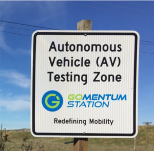
    Lors du voyage d’étude avec les membres du groupe de travail « moyens d’essais et homologation » du plan Véhicule Autonome France, organisé par Business France et CARA, j’ai eu à la fois l’opportunité de visiter plusieurs sites d’essais comme Gomentum à côté de San-Francisco et j’ai également eu la chance de discuter avec le Pr. Stephen E. Shladover à Berkeley, de l’importance du concept de « Contexte Opérationnel », connu en anglais sous le terme Operational Design Domain (ODD).

    Le concept d’ODD est essentiel puisqu’il permet de définir dans quelles conditions le système a été conçu pour permettre l’automatisation de la conduite. Il permet donc de spécifier les conditions opérationnelles à valider. Ce concept recouvre les dimensions du contexte : conditions climatiques, de luminosité ou l’exigence sur le parcours, etc. Pour bien comprendre ce concept, le niveau ultime de l’automatisation de la conduite (niveau 5) signifie que le véhicule devra être capable de rouler « partout et en toutes circonstances, par tous les temps sur n’importe quelle route, chemin ». Il existe dans l’industrie une grande confusion autour de cette définition des niveaux d’automatisation. Certains acteurs dans une volonté de simplification ou de positionnement marketing ayant associé le niveau 5 à un véhicule sans volant et sans pédales… alors qu’il s’agit en général d’un robot avec un niveau 4 et un ODD très limité. Autant dire que personne ne travaille aujourd’hui sur le niveau 5.

    Note : Le Pr. Stephen E. Shladover, est un des pionnier des ITS (Intelligent Transportation Systems) et a participé à la création du “California PATH”, le premier programme de recherche aux Etat Unis sur les ITS  en 1986. Il est aussi un des rédacteurs de la norme SAE avec les 5 niveaux d’autonomie. Pour en savoir plus : http://www.path.berkeley.edu/

    Vers des modèles probabilistes de perturbation

    Le problème est alors déporté sur la représentativité de ces modèles. En effet, cette approche nécessite d’abord de disposer de modèles de capteurs qualifiés qui soient représentatifs du comportement des capteurs… y compris face à des perturbations. C’est un premier verrou que le projet Simulation pour la sécurité du Véhicule Autonome (SVA) de l’IRT SystemX tente d’adresser aujourd’hui pour les capteurs optiques et les radars afin de mettre au point des modèles probabilistes de perturbation.

    Afin de mettre au point les modèles qualifiés avec un niveau de représentativité maximal, il apparaît nécessaire de pouvoir « Court-Circuiter » la partie physique des capteurs à modéliser pour alimenter directement l’algorithme de traitement à partir d’un environnement émulé, sous réserve de disposer de ce module fournisseur ce qui n’est pas le cas aujourd’hui. Ceci nous permettrait de construire des modèles probabilistes ou éventuellement d’exploiter directement ces modules probablement sous réserve des contraintes du temps réel.

    Dans le cas où on ne dispose pas de cet accès direct à la couche de traitement, un modèle « oracle » ou boite noire du capteur pourra être mis au point, ce travail est actuellement en cours pour la caméra. On peut imaginer que les équipementiers pourraient eux-mêmes fournir des modèles de capteurs qualifiés permettant de les tester en MIL.

    L’avantage considérable de cette approche est l’aspect temporel et parallélisable des tests. Il devient possible d’imaginer informatiquement un passage à l’échelle massif afin de jouer des milliards de tests en continu.

    Afin que ces tests soient représentatifs des conditions opérationnelles réelles, on peut s’appuyer sur les retours d’expériences des essais physiques sur pistes ou sur routes ouvertes afin de collecter les paramètres et d’avoir une approche probabiliste de leur distribution selon les cas d’usage.

    Dans une approche numérique, les cas d’usage servant à la validation du véhicule autonome sont construits soit à partir de situations créées dans la phase de conception du système, soit à partir de retours d’expériences. En Allemagne, une forte activité est déployée pour définir et créer une base de données regroupant des cas tests. Notamment au travers du projet PEGASUS qui vise à définir les scénarios à risque à tester en simulation : les accidents répertoriés en Allemagne (Base GIDAS) servent de sources de données, permettant la reconstruction des scénarios dans un environnement de synthèse (IPG Carmaker).

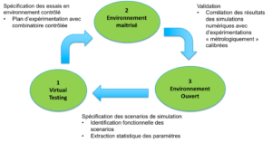
    La méthodologie développée dans le projet SVA de l’IRT SystemX et des partenaires (All4Tec, Apsys, Assystem, CEA, Continental, Inria, LNE, Optis, Oktal, PSA Peugeot Citroën, Renault, Sector, Université de Versailles Saint-Quentin-en-Yvelines, Valeo) consiste à construire une bibliothèque de scénarios et de terrains associés. Ces scénarios sont ensuite instanciés pour valider le système à tester comme par exemple un Traffic Jam chauffeur ou un Highway Pilot. Cette instanciation en fonction du système et de la variabilité de l’environnement permet de constituer les fiches de test pour la validation MIL (Model in the Loop), SIL (Software In the loop) et HIL (Hardware in the Loop).

    Des systèmes automatisés d’aide à la conduite tels que  Traffic Jam Chauffeur et Highway Pilot ne sont pas conçus pour le même contexte opérationnel (ODD) et leur validation doit être adaptée : dans le cas du Traffic Jam Chauffeur, on spécifie la vitesse maximale à 70km/h autorisant donc en cas de problème une manœuvre de mise en sécurité par un simple arrêt sur la voie de circulation.

    La bibliothèque de scénarios de tests pour la voiture autonome, construite dans le cadre du projet SVA, est partiellement fondée sur les scénarios fonctionnels de haut niveau spécifiés par des experts décrivant les situations auxquelles le véhicule sera confronté (cut-in, insertion, etc.). Une étude de sensibilité des paramètres permet de produire des scénarios logiques avec une variabilité cohérente à partir d’une situation initiale donnée.
    Intégration des essais virtuels dans la stratégie globale de validation du VA

    Le projet SVA complète la construction des scénarios de haut niveau décrits ci-dessus par des scénarios issus des enregistrements réalisés sur route (projet Moove de VEDECOM) et de la base d’accidentologie « VOIESUR » mise à jour régulièrement par le LAB et le CEESAR. L’analyse de ces enregistrements et l’exploitation des bases d’accidentologie fournissent des données statistiques sur la répartition des paramètres laissés variables dans les descriptions de haut niveau, comme par exemple : les positions des marquages et des acteurs ainsi que les vitesses et les accélérations des acteurs. Ces données statistiques permettent de mettre au point des scénarios concrets, en fixant l’ensemble des paramètres, pour réaliser des simulations représentatives.

    Par ailleurs, le projet SVA propose une approche formelle complémentaire qui vise à générer automatiquement des cas tests à partir d’une formalisation mathématique et d’une analyse comportementale en sûreté de fonctionnement.

    « Tests augmentés » et stratégie industrielle de validation tout au long du cycle de conception

    Un challenge supplémentaire est de tester les décisions prisent par l’AD (Automated Driving) qui peuvent avoir une influence sur le comportement du véhicule (piloté par l’AD) dans son environnement. Il faut alors introduire une rétroaction. En effet dans ce cas, suivant le comportement du véhicule (piloté par l’AD) dans l’environnement les données fournies par les capteurs peuvent varier. Par exemple, si les données utilisées vont servir à détecter si le système demande un freinage d’urgence ou non dans une situation donnée, il n’est pas nécessaire de mettre en place une boucle de rétroaction. Cependant, si on veut suivre l’évolution dans le temps, par exemple suivre comment l’AD suit le véhicule qui le précède, il faut mettre en place une boucle de rétroaction qui permet de réinjecter, de façon itérative et selon un pas de temps donné, la vitesse du véhicule sous test dans la simulation de l’environnement afin d’adapter le comportement des acteurs aux consignes données par le système de décision.

    Finalement, on devra se poser plusieurs questions avant de se lancer dans une virtualisation des essais pour les systèmes de conduite automatisés :

    • Le système sous test est-il une boite noire : intègre t’il les capteurs et la fusion des données de façon modulaire ?
    • Est-il possible d’injecter des données au niveau du traitement du signal des capteurs et d’accéder aux données qui seront fournies à l’AD avant la phase de fusion ?

    Selon quel domaine/context  (ODD) doit on valider la “Safety of the Intended Function” (SOTIF) ?
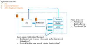
    Les questions à poser avant de mettre en œuvre des essais virtuels

    Il existe bien entendu une multitude d’options visant à offrir un « mix » entre l’approche MIL et HIL afin de remplacer, au fur et à mesure de la maturité des systèmes à tester, les modèles par des capteurs. Dans ces approches hybrides, il conviendra de toujours se poser la question de la représentativité de la réaction des capteurs face à une scène simulée.

    Dans l’hypothèse où l’on parvient à intégrer des perturbations représentatives ou des obstacles virtuels réalistes dans des scènes numériques issues d’essais réels afin de réaliser une validation, on pourrait alors parler de « Augmented testing »/« Tests Augmentés » comme on parle déjà de « Augmented reality »/«Réalité augmentée ».

    Il apparaît que Waymo met au point un système de simulation entièrement numérique permettant de plus de produire une variabilité des scènes virtuelles à partir de situations et de données enregistrées. Ils annoncent ainsi faire fonctionner 25 000 voitures virtuelles sur les rues numérisées d’Austin, de Phoenix et de Mountain View. D’après eux toujours, ces simulations réalisent chaque jour près de 13 millions de kilomètres. Soit au total 4 milliards de kilomètres ont été parcourus en 2016. En comparaison, les voitures de tests n’ont roulé que 5 millions de kilomètres pendant la même période.

    Il semble donc que Google combine des données récupérées sur route avec celle provenant de pistes en fonction des scenarios qui posent problèmes à ces voitures. Une fois suffisamment de données emmagasinées, les ingénieurs fabriquent un environnement spécifique pour y entrainer le logiciel.

    De quoi étudier des cas de figures inimaginable sur route : vitesse élevée, accidents, milieu urbain très dense… comportement irrationnels d’autres conducteurs.

    Sur la base de ce principe il devient imaginable de numériser des environnements classiques et de se focaliser sur les zones géographiques ou les contextes opérationnels (jour, nuit, météo) étant les plus intéressants au sens de l’incidentologie.

    À la suite de l’accident impliquant un véhicule Uber en Arizona en mars 2018, le CEO de Waymo a donné quelques chiffres intéressants sur le nombre de kilomètres entre 2 reprises en mains avec en moyenne 1 reprise en main tous les 5600 miles contre 1 tous les 13 miles pour le véhicule Uber.

    Le nombre et la qualité (et le coût) des capteurs est certainement à l’origine de cet extraordinaire écart avec 7 lidars, 7 radars, et 20 caméras pour Waymo contre 1 lidar, 10 radars et 7 caméras pour le véhicule Volvo modifié par Uber.

    Néanmoins, on peut aussi légitimement poser la question de l’influence de la méthodologie de « simulation augmentée » sur l’amélioration des performances de Waymo en matière de reprise en main.

    La stratégie de validation des véhicules autonomes passera par une articulation fine entre les essais sur route ouverte, les tests virtuels et essais sur pistes contrôlées.


  • Augmented Reality: an Ally for Automated Driving System

    Augmented Reality: an Ally for Automated Driving System

    Nowadays, more and more cars embed a Head Up Display (HUD), device integrated inside the dashboard and behind the cluster, which generates a virtual image seen in superposition on the road and displays relevant information to the driver, like speed, GPS data… This equipment has proved in few years to bring convenience in the driving experience, as well as safety as it increases the time the driver spends watching the road, and not looking for information in the cluster.

    Already on the rise, the next generation of HUD will integrate Augmented Reality (AR) concepts, where the virtual content will be even more linked to the real scene, like highlighting elements on the roads (pedestrian, traffic lights…) or interacting with it by coloring roads to be taken with GPS assistance. Despite looking simple, these differences increase the complexity of design and requirements on HUD system.
    And on the verge to this new technology, the question is often asked to the usefulness of such concepts in the autonomous car environment. We will see that at the contrary of the usual opinion, Augmented Reality appears more and more as a great asset for the future of autonomous driving.

    HUD and AR HUD: how it works and what are the main differences?

    The current HUDs in the automotive market display a virtual image on the road just above the hood of the car and provide simple but key information to the driver. A typical Human Machine Interface (HMI) provides status of speed of the car, the gear used, GPS information, fuel gauge… The main goal is to increase the attention of the driver on the road while giving him/her more easily the status of the car without the need to watch information on the cluster or any screens in the central column.
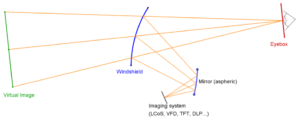
    A HUD is composed of an imager that generates an image (e.g. VFD, TFT, DLP…), and an optical part (a mirror in vast majority of systems), that will conjugate and project the image to a given distance. The projected image is said to be virtual, as it is seen by the driver as “floating in the air”.
    The following schematic shows the key parts of any windshield HUD: imager, freeform mirror and windshield:

    The optical systems, composed by complex shape surfaces, is designed in such a way that the orientation of the rays at the exit of the last optical surface (windshield in most cases) will force the eyes to accommodate on an image, placed at a long distance, hence the definition of virtual image. The virtual image could only be seen in an area called eyebox, limited due to different constrains (size of mirrors, size of system, requirement on brightness of the system…). The typical size of an eyebox is at least 130mmx60mm and is moved in height depending on the size of the driver (movement of ±60mm in most design).

    But right now, those pieces of information are related to status of the vehicle or its close vicinity, e.g. proximity of an object in the blind spot area, but are not directly linked to the environment. So, a natural evolution of such a concept would be to correlate the virtual display with the real scene and the results of this fusion will give a direct and seamless information to the driver. Several examples come to mind to any reader:

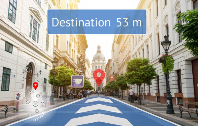
    • highlight the road to be taken in relation with GPS with vibrant colors,
    • frame in real time a pedestrian crossing the street,
    • detect and display road signs or traffic lights,
    • write content in relation with the environment named roads at a crossroad, possible parking lot, restaurants reviews…

    The figure below shows an artistic view of such concepts:

    This correlation to the real scene with a virtual image is often referred in the press or in the literature as Augmented Reality. Despite that the term of Augmented Reality could cover a larger span of applications depending on the fields (e.g. ref to “Le traité de la réalité virtuelle”, volume 1 – 5, Presses des Mines), the definition in the automotive field is rather straightforward: Display to the driver a virtual content superposed on the real scene, in real time.

    But the evolution from the day to day HUD, equipped in an increasing number of cars, to a truly augmented reality experience, is not just an upscaling from an existing technology. Some requirements are deeply redefined in the process and four of those main requirements will be exposed here:

    • Projection distance,
    • Field of View (FOV),
    • image position in space,
    • latency.

    Projection distance
    The projection distance is the distance between the driver’s eyes and the position of the virtual image. From another point of view, it’s the distance perceived by the driver to where the image is.
    This distance is chosen and fixed for each design, as it is still difficult both technically and financially to have a dynamic projection distance, for a mass production device.
    In a classical HUD design, ergonomic clues and feedback have suggested that the virtual image for a classical use should stay in the vicinity of the car. That’s why the virtual image is often put at the front end of the car’s hood. In the vast majority of cases, it is set to 2m, but a range between 1.5m to 2.5 is also a safe assumption.
    In an AR HUD design, this virtual image is put at a long distance in order to be better superposed the virtual content to the location of the actual cases, like highlighting cars, pedestrians, road signs… It is then chosen on average or depending on the use cases, and acceptable values could vary from 5m to 15m and more. This modification contributes to largely increase the complexity of the optic and mechanic (optomechanic): more power mirrors, higher sensibility in the assembly, increase in volume and weight…

    Field of view
    The size of the image is given by an angular description. The driver sees an image through 2 directions, i.e. the vertical Field Of View (FOV) and the horizontal FOV (see figure before).
    In the recent HUD world (end of 2017), the values are around 6°x2° (Horizontal x Vertical) and are evolving to 7°x2°, or even greater (the last Lincoln Continental has a 10°x2.5° at 2m projection distance). The vertical dimension is at the moment restricted by the current design of volume available under the dashboard and behind the cluster. To give an idea of the evolution of the image sizes, in 2014, the HUD displayed FOV of around 4.5°x2°, which will result a virtual image of 158mm x 70mm at 2m projection distance.
    For AR, the real scene is enriched with virtual data and therefore be ideally at the FOV of the human eye (or at least 20°x10°, cf. K.Bark, C.Tran, K.Fujimura, V.Ng-Thow-Hing. Personal navi: benefits of an augmented reality navigational aid using see-thru 3D volumetric HUD. AUI conference. 2014).
    At the moment, the requirement of the vast majority of use cases for an AR system is to have a FOV of 12°x4°. In the horizontal direction, the larger the FOV, the larger the portion of the road will be covered. In the vertical direction, it is directly linked to the portion of the road covered by the virtual image. In a 4°, the virtual image will cover the road from 15m to 80m. For even richer experience, it could be interested to highlight elements higher than the horizon line (e.g. road signs).

    Image position
    For any HUD, the driver needs to adjust the system to see a bright image. In the system itself, this adjustment is done through a kinematic system which will tilt a mechanical part of the system (majority of the time, it’s a mirror in the optical design). The consequence is that the virtual image will move according to this adjustment and it is seen higher on the road for a small driver and lower on the road for a tall driver. An analogy of a swing could be used: tall people need to receive the light coming from the system higher in the driver seat than smaller people and it forces the virtual image to go down. In the figure at the beginning showing a simplified HUD, the eyebox (on the right) of tall people needs to be moved upward (tall people are “higher” in the seat), and by consequence, the virtual image (on the left) moves downward. This aspect is not perceived by the drivers, as this adjustment is done once, and the virtual image has no connection with the road.
    In an AR system, the image, or at least the virtual content, has to stay fixed in space. Any movement of the virtual image involves wrong coincidence with the real scene, which results to a different experience between a small and a tall driver.
    To this regard, the image position in an AR HUD needs to be controlled, whereas it has never been an issue with traditional HUDs. This is a brand-new topic in regard with HUD design, such that an eyetracking system (or even an headtracking would be sufficient) could be mandatory in order to offer the best coincidence between virtual and reality contents while minimizing the error of superposition between these two, due to their difference of position in space (reminder: projection distance would be fixed at first). This later aspect is sometimes referred to parallaxes’ issues.

    Latency
    In virtual reality, in augmented reality or even in mixed reality with see-through glasses, the delay between the movement of the observer (head rotation, eye movement…) or the modification of the scene and the update of the virtual content in the virtual system must be extremely short. This delay is called latency.
    Studies suggest a maximum threshold at 20ms in the case of augmented reality, and also advise to not go upper 7ms in mixed reality, in the risk to experiment discomfort, discontinued stress, headache, and at the end, a rejection of the system by the user.
    Solutions to reduce latency are linked to the technology used and we don’t feel relevant to draw a long comprehensive list. The main idea is always to find tricks on the implementation and on the conception, in particular on the rendering engine or on the driver or on the hardware.


    Cues to the advantages of AR in Autonomous Conditions

    The autonomous car is clearly one of the biggest trend in the car world of the past couple of years, as seen in motor or consumer shows, and the potential of such a system is already tangible: increased safety and reduction in accident outcomes, traffic optimization with an increase of traffic flow, freeing the driver, and the list goes on and on.
    But before being at this dream stage of a full autonomous car, the experience of autonomous driving is currently categorized in levels with different possibilities. From level 0, where the driver is warned by the car but is still in control, to level 3, where the majority of the action is taken by the car, to level 5, where human assistance is seen as optional. At the moment, the car will obviously still require some assistance of the driver to overcome unknown situations (around level 2 to 4), and is sometimes referred to as cooperative driving mode. The car executes some defined actions (accelerate or brake, turning, etc) but requires the assistance of the driver to take some decisions (choosing the best lane, handle some key maneuvers).
    This is where Augmented Reality comes into play, as it will offer a set of tools for the driver to interact with the car, and for the car to communicate intelligible information to the driver.
    During the project Localisation and Augmented Reality, studied at IRT SystemX, use cases were studied in simulator and on a car equipped with an AR HUD prototype to define the correct visual grammar on the relevant objects of the environment. The following pictures show the tools or rendering used to study the link between autonomous driving and AR system, or the use cases of AR systems.

    IRT SystemX driving simulator setup: projection scene with car cockpit as close as possible as a real one: driving wheel and pedals, gear box and lever, simplified HUD composed of flat panel and PC monitor, safety belt, rear mirrors.
    Picture of a real scene with superposed virtual image generated by the AR windshield HUD system, embedded in a car, on a mannequin.

    During these studies, Augmented Reality appears to be a great asset to annotate the roads: highlight proximity cars or obstacles, and relative speed/distance to them, direction to be taken, key elements of the scene (pedestrians, traffic lights…).
    On another level, it is not uncommon to hear concerns about the autonomous car, in particular on a trust level: lack of confidence of consumers, fear of inefficiency or accidents.
    Again, a virtual image, collocated to the environment, will provide a complex and powerful communication pipe between the car and the driver. The different elements on the road, quoted before, will be highlighted by the AR system. The driver will know at any moment what the car understands about the environment and its vicinity and what decisions it is taking (merging in traffic, stopping because a danger has been identified…). The goal is to give the confidence to the driver that the car is able to handle the complexity of driving.
    For all the reasons exposed, it appears to us that autonomous driving and augmented reality are antagonist is a false assumption. At first, augmented reality could be a great asset for autonomous car, for both early adoption and integration to cooperative driving.


    Conclusion

    After many years of attempt in different fields (avionic, military, consumer market, automotive), there are nowadays many converging features that make it possible to integrate an Augmented Reality system in a car and have a convincing experience. Indeed, on the technical part, the emerging market of HUD in car affords to use luminous imagers at reasonable prices, even if some technical feats still need to be challenged or overcome.
    And on the software aspect, the smart detection devices, driven by the autonomous car market, are able of more and more recognition of objects in the driving scene.
    The user testings of Augmented Reality’s use cases were done in IRT SystemX through different approaches:

    • with a simulation cave (mockup cockpit with hemispheric projection screen),
    • with real devices, as AR head-up display prototype in a car (BMW X5).

    Simulation is a powerful tool that allows to establish the minimum and desired requirement of the applications, or to quickly debunk HMI ideas, behaviors of cars and drivers while controlling the experiments in safe conditions and having sharp elements to use and to compute (positions of simulated vehicles, working with low latency, etc). The studies conclude that AR HUD is a powerful system to pair with autonomous car, as it will help the driver to have a better understanding of the environment and to take over more easily the driving, when passing from autonomous to cooperative or non-autonomous mode.

  • Le rôle des Instituts de Recherche Technologique dans l’écosystème de la mobilité du futur

    Le rôle des Instituts de Recherche Technologique dans l’écosystème de la mobilité du futur

    Pour répondre aux enjeux de l’urbanisation croissante du monde et de la transition énergétique et environnementale, les mobilités de demain seront multimodales, à la demande, partagées, en grande partie autonomes et fortement connectées, à propulsion électrique pour une part significative, à faible impact environnemental. De nombreux défis technologiques, scientifiques, économiques, juridiques, d’usage, devront être relevés avant leur déploiement opérationnel à grande échelle à l’horizon 2030.

    La résolution de ces défis appelle les contributions et compétences d’une multiplicité d’acteurs que sont les fournisseurs de véhicules (automobiles, bus, tramway, trains, etc.), les fournisseurs de technologies (numérique, batteries, matériaux, infrastructures, etc.), les opérateurs de mobilité (privés, publics), les compagnies d’assurance, associées à celles de laboratoires de recherche académique et de start-up du domaine, très nombreuses et dynamiques.

    Les innovations qui donneront naissance à la mobilité de demain et aux nouveaux usages proviendront pour une part significative de l’interaction entre les différents acteurs de cet écosystème, interaction qui prendra notamment la forme de travaux de R&D, dont la couverture s’étend depuis la recherche amont en modélisation des mobilités, en science des données et outils d’optimisation et de recherche opérationnelle, jusqu’au développement et l’intégration des technologies dans des systèmes de plus en plus complexes. Par exemple, la sécurité et la sûreté de la mobilité de demain devra proposer des gains significatifs par rapport à l’état de l’art actuel, ce qui nécessitera des travaux de R&D associant approche scientifique et technologies de pointe, articulés avec les dimensions éthiques et juridiques.

    Les Instituts de Recherche Technologique (IRT) créés en 2012 dans le cadre des Investissements d’Avenir présentent la caractéristique d’associer la recherche de nature académique avec le développement et le transfert technologique propres aux entreprises, principalement en mode multilatéral, depuis la start-up jusqu’à la grande entreprise, en passant par l’ETI et la PME, de manière à maximiser les interactions et l’impact de compétitivité.

    Pour les pouvoirs publics, autorités organisatrices et financeurs des infrastructures, être associé aux travaux de R&D des IRT regroupant ses partenaires, sera un gage d’efficacité des expérimentations sur le terrain, essentielles à l’adaptation et la validation des innovations pour les territoires concernés.

    C’est ainsi qu’en tant que passerelle entre les différentes composantes de l’écosystème de la mobilité de demain et le monde des sciences et des technologies, les IRT occupent une place essentielle pour contribuer à l’invention et au déploiement de nouvelles solutions pour une mobilité propre et durable, flexible, et capable d’accompagner la croissance des besoins des acteurs socio-économiques, que ce soit les citoyens ou les entreprises.

    Cet article est extrait de livre blanc « RÉINVENTER LA MOBILITÉ URBAINE ET PÉRIURBAINE À L’HORIZON 2030 : 24 propositions pour l’Île-de-France dans le cadre de Paris 2024 ».

  • Smart Mobility: SystemX contributes to the future of mobility in Singapore

    Smart Mobility: SystemX contributes to the future of mobility in Singapore

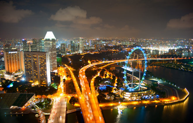
    In 2014, Singapore has launched its Smart Mobility 2030 program, dedicated to “moving towards a more connected and interactive land transport community”. Three years later, many initiatives have been rolled out across the Lion City. Here is a summary of this journey towards e-transport.
    The Institute for Research and Technology SystemX@Singapore, which as recently established itself in Singapore, is contributing to this effort by joining the CETRAN (Centre of Excellence for Testing & Research of AVs at NTU) project, aimed at testing and certifying the autonomous vehicles.

    Here is the problem statement to be solved: M. Tan lives in an island of 720 km², with a population of 5,6 million inhabitants, meaning a density close to 8,000 people/km², third most dense country in the world after Macau and Monaco. In the meantime, M. Tan and his fellow-citizens have built a 50 years old fast-growing economy (also 3d in the world by GDP/capita), that is likely to attract more and more people in the near future. Among these people are the elderly that will represent a bigger part of the whole population[1]. Altogether it means a confined land, packed with people, many of them with challenging mobility capacities, but most of them, including M. Tan, willing to take advantage of the new technologies enabling faster, easier and more convenient mobility. This is the problem statement Singapore has to face and solve in the coming years, so as many growing megacities. As part of the solution is the Smart Mobility 2030 strategic plan, issued in 2014 by the Singaporean government, providing the multiple keyplayers of this challenge with a roadmap.


    Smart Mobility 2030 Strategic Plan

    The so-called “Intelligent Transport System (ITS)” encompasses a wide range of solutions such as road networks optimisation, new public transport systems, incident management, as well as safety improvement. This has already led to the launch of the world’s first fully automated underground driverless Mass Rapid Transit line (MRT). E-payment with the Contactless e-Purse Application Standard (CePAS), the Electronic Road Pricing (ERP), or the Electronic Parking System (EPS) have also been instrumental in optimising people and vehicles’ traffic, hence reducing congestion.

    As for the future, connectivity and interactivity are keys to success. The travel experience will be composed of real-time information on-the-move, shared within the community, and beneficial for diverse groups of users including the elderly, the mobility-challenged, and the cyclists[2].

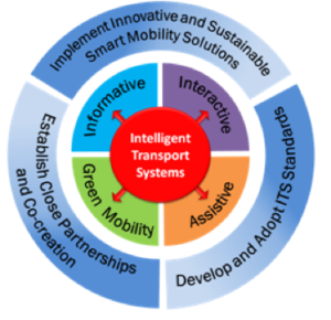
    The Smart Mobility 2030 roadmap relies on three strategies and four focal areas:

        LTA
    • 1st strategy: Implement innovative and sustainable smart mobility solutions
      Cost-effective solutions for diverse transport users and use of big data analytics to facilitate travel planning and management
    • 2d strategy: Develop and adopt ITS standards
      Need for accurate, shared, reliable, transport data, together with homogenised standards and protocols for ensuring inter-operability.
    • 3d strategy: Establish close partnerships and co-creation
      Foster public and private collaborations. Leverage on each other’s expertise and skills.

    To implement these strategies are the four focal areas:

    • Informative: Information on-the-go will become a “must have”, for a more mobile and more connected population. Data collection will rely on location systems (Global Navigation Satellite Systems), high definition video capture, as well as other means of sensor collection. Sensor deployment will have to minimize infrastructure impact while maximising data collection. Smart processing and algorithms will be key in facilitating the downstream data analysis. This huge amount of data will require appropriate technologies to manage big data and clear visualisation tools. Formats, interfaces, and protocols, will need to be harmonised, shared, and yet secured, as far as privacy and anonymity is concerned.
    • Interactive: Intelligent fleet management systems will become keys in many sectors as public buses (bus arrival times and load information), car-sharing on demand, smart logistics (faster goods delivery). Sharing of transport information between agencies, transport operators, emergencies, will lead to more effective and coordinated responses. Spatial and contextual information will be delivered to individuals and provide them with personalised content.
    • Assistive: In-vehicle on-board devices will provide warning information to drivers, thanks to for instance traffic light controls at traffic junctions. The development of V2V (Vehicle to Vehicle) and V2I (Vehicle to Infrastructure) technologies will also enable safety communication and reduce the number of accidents. These telematics applications should expand to dynamic routing, intelligent parking guidance, and real-time traffic news. A big part of this assistive future will rely on self-driving or autonomous vehicles. These driverless vehicles (cars, buses, trucks) will eliminate human errors, optimise road capacity, and lower carbon emissions. Nevertheless, in addition to technological issues, many regulatory obstacles will have to be overcome.
    • Green Mobility: Higher usage of public transport, “greener” vehicles (hybrid, electric), regenerative brakes in trains are examples of usages or technologies that reduce the impact on the environment. The development of new infrastructures for ITS equipment will require environmental-friendly conception, so as to minimize their own impact. Data centres use a lot of power and will require the optimisation of resource sharing through cloud computing or other solutions.


    Smart mobility initiatives in Singapore

    Today, in 2017, Singapore has rolled out many initiatives to address this 2030 agenda[3].

    For example, smarter bus systems, thanks to the Common Fleet Management System (CFMS), enable operators to monitor the location and performance of their bus fleets, and actively work with their bus captains to adjust bus operations in real-time.

    The Land and Transport Authority (LTA) is also developing a Fusion AnalyticS for public Transport Emergency Response (FASTER) system which will combine data from various sources, including fare-card, video and telecommunications systems, to perform analytics. It will enable LTA and the operators to visualise commuting patterns to improve transport planning, and it also triggers early alerts of crowd surges and transport incidents.

    The next-generation Electronic Road Pricing System, which is based on Global Navigation Satellite System technology, will enable the collection of comprehensive, real-time, aggregated traffic data, and disseminate such directly to motorists, to enable them to better plan and optimise their travel routes.

    The LTA has also been conducting trials of hybrid and electric buses. After promising first results, the objective is to run 50 hybrid and 60 electric buses, that is to say three bus services fully served by electric buses.

    As part of Singapore’s Electric Vehicle (EV) Phase 2 Test-bed, which aims to explore the viability of operating fleets of EVs for car-sharing and of electric taxis, LTA and the Economic Development Board (EDB) worked with HDT Singapore Taxis Pte Ltd to bring in Singapore’s first fully-electric taxi fleet. HDT began operating its fully-electric taxi service in September 2016, and progressively deploys 100 e-taxis by mid-2017 as part of an eight-year trial.

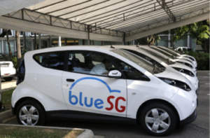
    LTA and EDB partnered BlueSG Pte Ltd to launch the BlueSG EV car-sharing programme, which will see 1,000 shared EVs deployed across all HDB towns by 2020, and the installation of 2,000 charging points island-wide. The first batch of 125 Bluecars and 250 charging points will be rolled out by the second half of 2017.

    BlueSG

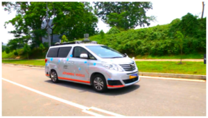
    Lastly, a lot of efforts have been made in the field of autonomous vehicles. For about 2 years, many trials have started across the country. In September 2016, LTA doubled the length of the test routes within One-North from 6 to 12km, after AV trial participants showed their capabilities in navigating mixed traffic environments. Since then, the AV trial participants have demonstrated a readiness to advance their capabilities to more on-road scenarios in an expanded test area. In June 2017, new areas such as the National University of Singapore (NUS), Singapore Science Park 1 and 2, Dover and Buena Vista, have been opened to AVs trials. These areas present a larger test bed, and will add another 55km to the existing AV trial routes.


    Autonomous trials in Singapore in 2017[4]

    • A*STAR’s Institute for Infocomm Research (I2R): first self-driving vehicle to be approved for public road testing at One-North since July 2015.
    A*STAR
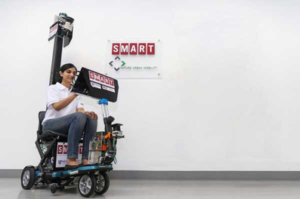
    • National University of Singapore (NUS) and the Singapore-MIT Alliance for Research and Technology (SMART): testing a fleet of self-driving golf-buggies. A retrofitted electric passenger car was the second vehicle to be approved for more complex testing on public roads. A prototype of a four-wheel self-driving Personal Mobility Device was also unveiled for public trial in November 2016.
    SMART
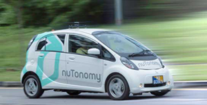
    • Delphi automotive and nuTonomy: the first private company – and the third applicant – to obtain approval for public road testing at One-North as of April 2016. Aim to launch a commercial autonomous mobility-on-demand service.
    nuTonomy
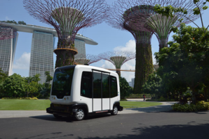
    • Gardens by the Bay, French company EasyMile in collaboration with ST Engineering: the EasyMile driverless shuttle went for public trial in December 2015 and is now in service at Gardens by the Bay. On 22 June 2016, Gardens by the Bay launched the Auto Rider for public rides.
    EasyMile
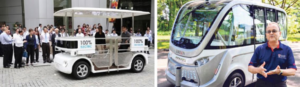
    • French company Navy, in collaboration with Energy Research Institute (ERI@N) at Nanyang Technological University (NTU): self-driving golf cart and electric shuttle around NTU can fetch up to 8 people and travel at a maximum speed of 20 km/h. These are part of NTU’s plans to eventually trial two full-sized autonomous bus in its campus in 2018.
    LTA, NTU
    • LTA and ST Kinetics: development of a 40-seater electric autonomous bus prototype.
    • MOT (Ministry of Transports) and PSA Corporation collaboration with Scania and Toyota: truck platooning trials over a three-year period from January 2017 to December 2019, the collaboration will enable heavy vehicles to move in leader-follower formation, as well as to fully automate the processes for precise docking and undocking of cargo.
    • Katoen Natie and VDL: 12 driverless trucks will go on trial on Jurong Island from September 2017. The trucks will be retrofitted with autonomous systems which will communicate with transponders installed in the road.


    In order to allow these autonomous vehicles to join the road traffic, government authorities like LTA will need to assess, test, and certify them so as to ensure the maximum of safety and convenience for road users. This is the scope of the Centre of Excellence for Testing & Research of AVs at NTU, namely the CETRAN project.

    What is CETRAN?

    The Land Transport Authority (LTA) and JTC (Jurong Town Corporation), in partnership with the Nanyang Technological University (NTU), launched CETRAN, at CleanTech Park on August 2016. On November 22d, 2017 the CETRAN circuit will be officially opened by the Singaporean Minister of Transport, M. Khaw Boon Wan.

    JTC

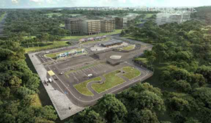
    CETRAN will spearhead the development of testing requirements for SDVs, for which testing will be carried out at the 1.8-ha CETRAN Test Circuit, which is jointly developed by LTA and JTC to provide industry players with a simulated road environment for the testing AVs prior to their deployment on public roads.

    In line with LTA strategy to establish public and private collaborations, NTU is partnering with four foreign entities to develop the CETRAN project. BMW, TNO, TUV-SUD, and SystemX will be each responsible for one workpackage of the project.

    The workpackage managed by SystemX will focus on digital modelling & simulation for safety & digital security, applied to autonomous transport. This is the first project of SystemX in Singapore, willing to develop others in the coming months, in the fields of autonomous transports, agile industry, smart territories, or internet of trust.


    [1] http://www.singstat.gov.sg/statistics/visualising-data/storyboards/population-trends

    [2] https://www.lta.gov.sg/content/dam/ltaweb/corp/RoadsMotoring/files/SmartMobility2030.pdf

    [3] https://www.lta.gov.sg/apps/news/page.aspx?c=2&id=e09102cd-acd5-469e-8234-777b68e4e18a

    [4] https://www.smartnation.sg/initiatives/Mobility/self-driving-vehicles-sdvs-future-of-mobility-in-singapore